

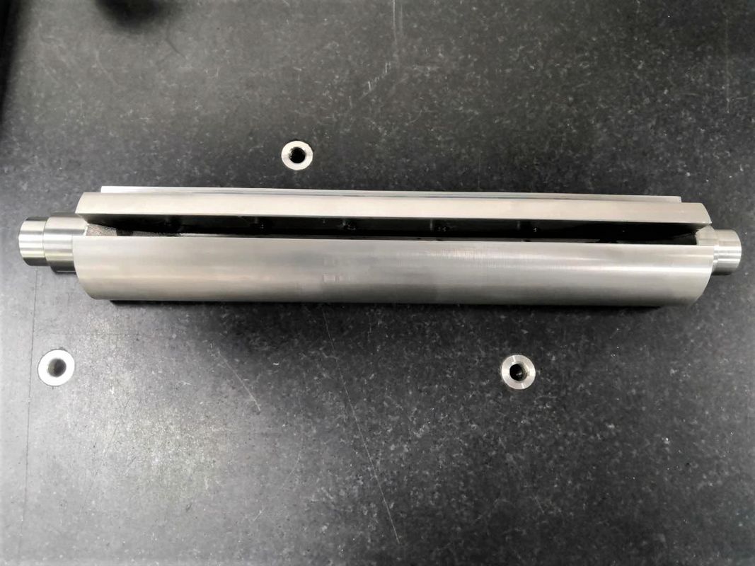
High Precision Custom Cnc Lathe Machine Parts Turning Milling Metal Brass Aluminum
High Precision Custom Cnc Lathe Machine Parts Turning Milling Metal Brass Aluminum Description
| Cnc Machining Or Not: | CNC Machining | Process: | Drilling/Bending/Stamping/Wire Cutting/Punching/Grinding/Welding |
|---|---|---|---|
| Service: | OEM/ODM/Customized/Design | Sample: | Available |
| Drawing Format: | IGES,PDF,STEP. STP,DWG,X-T | Material: | Brass,copper,Aluminum,Stainless Steel,etc |
| High Light: | cnc turned components, precision turned parts | ||
High Precision Custom Cnc Lathe Machining Turning Milling Metal Stainless Steel Copper Brass Aluminum
Product details:
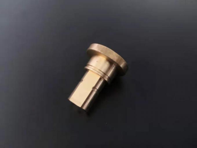
High Precision Spare Machine Partsspiral patternCover Shell of Electronic Products
Colour anodizing Appearance Parts Communication Equipment parts
Material: C3604 Rugosity:Ra0.8 Tolerance:0.02-0.05mm
L*W*H(mm)=15mm*15mm*28mm,
Main Product Display:
Metal:Aluminum2024,2A12,5052,6020,6061,6063,7075,45#,SKD11,DC53,SUS304,SUS136.Machine:CNC lathe,Centering Machine,Multi-Axis turning,Surface treatment:nickel plating,chrome plating,anodizing.Purpose:Semiconductor Machinery,Laser Cutting Equipment,Communication equipment,
Medical equipment,agricultural machinery,electrical appliances products,Generator parts,
Bathroom Parts,Ship accessories,Electric Tool Parts,Monitoring equipment,Communication
Equipment,Audio Equipment Parts,Digital Camera Parts,Mining Machinery Parts,
Petroleum Mining Machinery Parts,Juice extractor parts,Mountaineering Equipment Parts,
Fishing gear parts,Sports Equipment Parts,Fitness Equipment Parts,Photographic
equipment parts,Furniture Hardware Parts,Mower Parts
Processing all kinds of metal and plastic matenrials with the change of the times,the materials
chosen by customers are changing constantly,in order to meet the different material needs
of customers,we have accumulated a very rich and wide range of process characteristics
and technical know-how of mechanical processing of metal and non-metal materials through
continuous technological innovation and research and development.
KeyMachine Display:
Continuing to invest heavily in our facilities , we aim to bring you the most reliable,efficient
and affordablemetal component.our highly skilled and professional workforce is dedicated
to satisfying the individualneeds of all our customers and various markets the serve.
| Processing type | ||
| CNC Machining | EDM | Gear working |
| Multi-Axis CNC Machining | Thread Processing | stamping |
| CNC Turning Service | wire cutting | laser cutting |
| CNC Milling/Turning Multiple | drilling | Parts Assemble |
Production Capabilities Minimum Tolerance
Outer diameter dimension(turning Process) 0.01mm
Outer diameter dimension(centerless grinding process) 0.005mm
Outer diameter dimension(step grinding process) 0.005mm
Internal diameter dimension(turning process) 0.01mm
Center distance dimension( CNC milling process) 0.01mm
length,width,high(cnc milling process) 0.01mm
surface roughness Ra0.2a
Run-out 0.01mm
Roundness 0.01mm
Flatness 0.01mm
perpendicular 0.01mm
Cylindricity 0.01mm
Why are you choose us ?
1.Advanced facilities ensure the Top quality ,
over 80 sets high precision CNC machines
2. Same/Better quality with Germany ,USA
3. 20 sets 3,4,5 axis CNC from Japan and taiwan.
4. Certificate: ISO9001
5. 100% guarantee quality , lead time .
6. Reports available for PPAP,CPK,PFMEA,CONTROL PLAN etc
What is CNC?
The Basics Of CNC Machining
CNC (Computer Numerical Controlled) machining is a means to remove material with high precision machines,
using a wide variety of cutting tools to create the final design. Common CNC machines include vertical milling
machines, horizontal milling machines, lathes, and routers.
How CNC Machining Works
To successfully make a part on a CNC machine, skilled machinists create programmed instructions using CAM
(Computer Aided Manufacturing) software in conjunction with the CAD (Computer Aided Design) model
provided by the customer. The CAD model is loaded into the CAM software and tool paths are created based
on the required geometry of the manufactured part. Once the tool paths are determined, the CAM software
creates G-Code (machine code) that tells the machine how fast to move, how fast to turn the stock and/or tool,
and where to move the tool or workpiece in a 5-axis X, Y, Z, A, and B coordinate system.
Products categories
-
Multi Axis Cnc Mechanical Parts For Generator M...
-
Medical Machining Metal Four Aixs CNC Turning P...
-

Mechanical Parts Spindle CNC Turning Parts Lath...
-

SUS304 CNC Turning Parts Lathe Machining Thread...
-
Customized SUS304 Lathe Machining Thread CNC Tu...
-

Super long spindle 720mm Cnc Turning Machine Parts